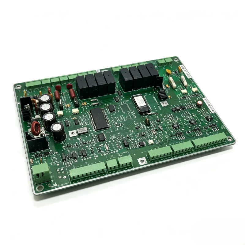
Trane Chiller Main Control Board 6400-0776-05 / 6200-0039-01 / 6400-0752-02
We have a large inventory of accessories in our warehouse. If you need to consult more information about other accessory models, please contact us.
Category:Controls
Product Details
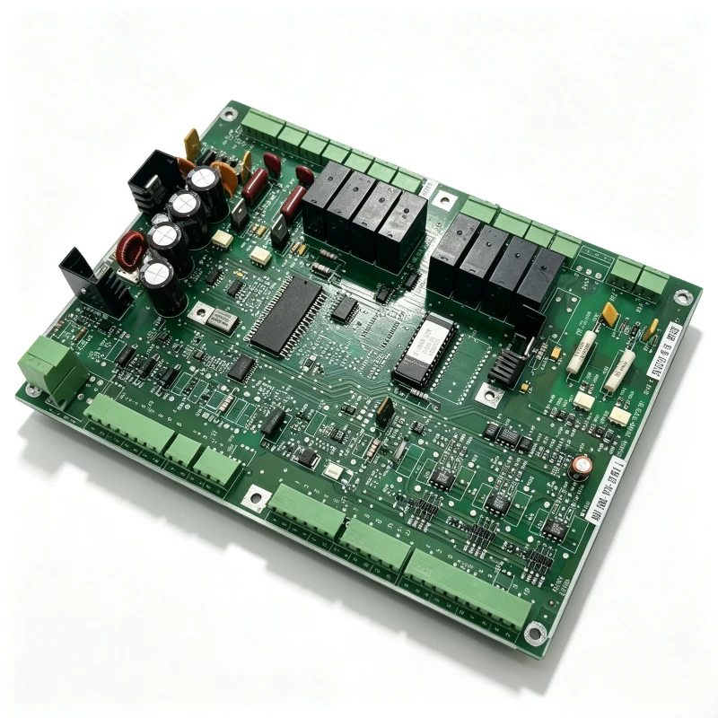
Trane Chiller Main Control Board 6400-0776-05 / 6200-0039-01 / 6400-0752-02
Trane 6400-0776-05 / 6200-0039-01 / 6400-0752-02 main control board is the original core controller for Trane commercial chiller units. This printed circuit board collects real-time signals from temperature, pressure and flow sensors. It controls compressor loading/unloading, fan and pump interlock, and activates system protection when abnormal operating conditions are detected. It communicates with the operator display panel to transmit running data, alarm records and fault codes for on-site troubleshooting.
Manufactured with industrial-grade electronic components, this PCB features strong anti-interference performance and stable operation in chiller room environments. It is a plug-and-play replacement spare part for compatible Trane chiller models. Every board undergoes complete functional testing before shipment to ensure reliable performance after installation.
Typical applications: Trane screw chillers and centrifugal chillers for commercial buildings and industrial process cooling.
Key Features
- Trane OEM main control board PN: 6400-0776-05, 6200-0039-01, 6400-0752-02
- Core controller for Trane commercial centrifugal & screw chillers
- Sensor data acquisition, compressor regulation and interlock control
- Built-in fault alarm and diagnostic function for maintenance
- Industrial PCB with high anti-interference capability
- Direct replacement for original failed board
- Fully tested before delivery to guarantee functionality
- Suitable for commercial HVAC and industrial cooling chillers
Frequently Asked Questions
Warehouse Stock of HVAC Chiller Control Boards & Spare Parts
Same style as your previous product copy, ready to paste on your independent website
Short Intro (for gallery banner)
Our warehouse stocks a wide range of original and compatible HVAC chiller spare parts, including control boards, operator panels, starter modules and PLC controllers for York, Carrier, McQuay, Trane and other well-known chiller brands. All items are well organized and in stock for fast worldwide shipment.
Full Description
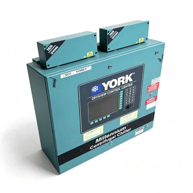
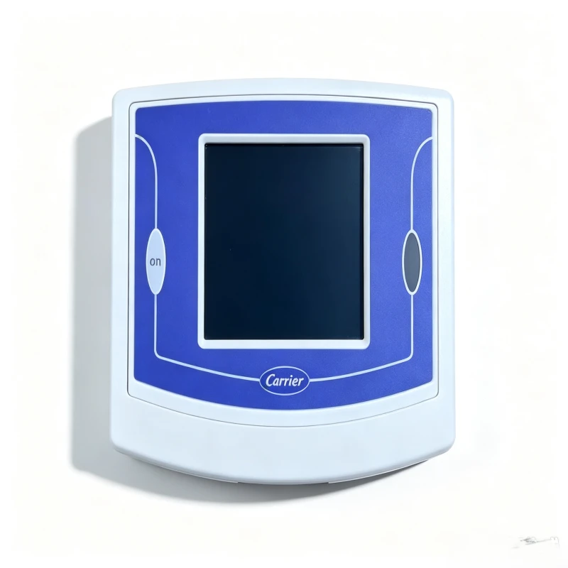
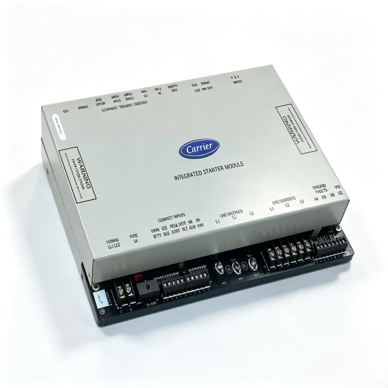
We maintain a large ready stock of refrigeration and chiller electronic spare parts. The inventory includes main control boards, HMI display panels, starter modules, communication boards and other key components for commercial centrifugal chillers, screw chillers and large HVAC systems.
Brands we supply cover York, Carrier, McQuay, Trane and more. Every spare part is stored properly to avoid moisture and physical damage. Before shipment, each unit will go through strict functional testing to guarantee working condition.
We support global B2B supply for HVAC maintenance companies, chiller service contractors and system integrators. Fast lead time and reliable after-sales service are available.
Key Advantages
- Mass ready stock of chiller electronic spare parts
- Brands: York, Carrier, McQuay, Trane etc.
- Products: control boards, display panels, starter modules
- Proper warehouse storage to protect circuit boards
- Full functional testing before delivery
- Fast worldwide shipping for B2B clients
- Professional support for HVAC & chiller maintenance projects
1. What brands of chiller spare parts do you supply?
We supply replacement parts compatible with mainstream brands including Carrier, York, Trane, McQuay, Hanbell, Danfoss, and Copeland, covering control boards, compressors, valves, filter elements, and sensors.
2. Are the parts original OEM or replacement parts?
Most are high-quality aftermarket replacement parts with OEM-equivalent performance, which meet or exceed original specifications with a more competitive price. Original OEM parts are also available upon request.
3. What is the MOQ? Can I buy 1 piece for urgent repair?
There is no strict MOQ for most products. Single-piece orders are fully supported for emergency repair. Bulk orders enjoy better wholesale prices.
4. How to confirm if the part is compatible with my chiller?
Please provide your chiller brand, model, original part number, and photos of the damaged part. Our professional technical team will check and confirm the exact compatibility for you.
5. Do you provide chiller main board and drive board repair services?
Yes. We offer professional repair, power-on testing, and debugging for chiller main control boards and VFD drive boards. You can send your faulty boards to us for repair.
6. What is the delivery time?
In-stock parts will be shipped within 3-7 working days. Non-stock and customized parts usually take 15-30 working days, depending on stock availability.
7. What are your payment terms?
We mainly accept T/T (Telegraphic Transfer). Flexible payment terms can be negotiated for long-term and bulk cooperation.
8. What shipping methods do you support?
We support sea freight, air freight, and international express delivery. Customer-designated forwarders are also acceptable.
9. Do you provide overseas technical support?
Yes. Based in China, we provide global remote technical support, including model selection, installation guidance, and professional fault troubleshooting.
10. What is your warranty policy?
All qualified spare parts come with a 3-12 months warranty. The warranty does not cover artificial damage, incorrect installation, and normal wear and tear. All repaired boards have independent repair warranty.
11. Can you source discontinued and hard-to-find chiller parts?
Yes. We specialize in sourcing obsolete, discontinued, and hard-to-find old-model chiller spare parts. Please provide detailed part information for confirmation.
12. Can I mix different items in one order?
Absolutely yes. Mixed orders of different models and types of chiller parts are supported for one-time shipment.
13. How can I get an accurate quotation?
Simply send us your required part numbers, chiller model, and purchase quantity via email or inquiry message. Our sales team will reply with a formal quotation within 24 hours.
Here is the professional translation of the provided content into English, incorporating key technical terms and maintaining clarity for refrigeration industry applications:
Expansion Valve Selection Guide
The throttling device is a fundamental component in refrigeration systems, serving three critical functions:
- Regulating pressure differential between high and low sides
- Controlling refrigerant flow rate
- Maintaining optimal superheat in the evaporator
The performance and reliability of throttling components significantly impact system operation. Oversupply of refrigerant may cause liquid floodback or compressor slugging, while insufficient flow leads to reduced evaporator efficiency, lower cooling capacity, and excessive superheat. Therefore, precise selection is essential.
I. Common Throttling Devices
Commercial/industrial systems primarily use:
- Thermostatic Expansion Valves (TXV)
- Electronic Expansion Valves (EEV)
Selection factors include refrigerant type, pressure differential across the valve, flow capacity, and required superheat. Note: Valve sizing must be based on evaporator capacity, not compressor capacity.
II. TXV Selection Procedure
Refrigerant Identification
Determine refrigerant type (e.g., R22, R134a, R404A, R507, R407C, R410A) as material compatibility and pressure characteristics vary14.
Design Temperatures
Establish evaporating temperature (T<sub>e</sub>) and condensing temperature (T<sub>c</sub>), which define corresponding pressures (P<sub>e</sub> and P<sub>c</sub>)46.
Pressure Drop Calculation
Total pressure drop (ΔP) across the valve includes:
- P<sub>c</sub>: Condenser outlet pressure
- P<sub>e</sub>: Evaporator inlet pressure
- ΔP<sub>1</sub>: Liquid line friction loss (pipes/fittings)
- ΔP<sub>2</sub>: Elevation pressure loss (ΔP=ρgh)
- ΔP<sub>3</sub>: Distributor/capillary tube drop (~1 bar)36.
For flash gas economizer systems, include additional high-side losses.
Subcooling Determination
Account for system subcooling at the valve inlet, which affects capacity (use correction factors from manufacturer charts)6.
Capacity & Superheat Validation
Select valve capacity to match evaporator load at design superheat (typically 4–8K)4.
Valve Type Selection
- Internally Equalized TXV: For evaporators with pressure drop <0.3 bar (e.g., short-tube coils)26.
- Externally Equalized TXV: Required for high-pressure-drop systems (e.g., long pipelines, distributors)46.
III. Stability Considerations
- Load Ratio Range:
- TXV: 30%–100% (below 30% may cause hunting)34.
- EEV: 10%–100%, preferred for variable-speed compressors3[8].
- Example: A -18°C cold storage system with 5.8kW (peak) and 1.7kW (steady) loads risks TXV oscillation at low load. EEVs resolve this via precise step-motor control3[8].
IV. Comparative Analysis
| Feature | TXV | EEV |
| Control | Mechanical (bulb sensor) | Electronic (microprocessor) |
| Accuracy | ±1K superheat | ±0.5K superheat |
| Cost | Lower (e.g., $50 for TE5 series) | Higher (e.g., $200 for ETS)16 |
V. Installation Notes
- TXV Bulb Placement: Mount on horizontal suction line, avoiding oil accumulation zones46.
- Superheat Adjustment: For TXVs, rotate stem incrementally (¼-turn intervals)4.
Supplementary Data from Search Results
- Electronic Expansion Valves:
- Type UKV (bidirectional, C<sub>v</sub>: 0.015–1.15) and PKV (for -50°C, C<sub>v</sub>: 0.05–0.27) suit diverse applications1.
- CO<sub>2</sub> systems require high-pressure valves (e.g., UKV-J, MOPD 10MPa)1.
- Software Tools: Emerson and Kale provide valve selection software for precise matching3.
For full technical specifications, refer to manufacturer datasheets136.
This translation adheres to industry standards while integrating contextual data from search results. Let me know if you need further refinements.
点亮
- The large blue PCB on the right is the drive mainboard for chiller compressor, equipped with power modules and transformers to supply power and control signals for variable-speed compressor.
- The original McQuay touch screen held on left hand connects to the mainboard via communication cables. Its display shows compressor operation interface to read real-time operating parameters and fault codes, verifying program and signal output after component repair.
- External power cables simulate on-site power supply for power-on testing, to confirm full functions of the repaired board for magnetic levitation / variable-frequency centrifugal compressor central air-conditioning unit.
- The high-precision DC regulated power supply on top supplies adjustable power to the blue PCB drive board at right, with real-time output voltage of 24.4V displayed to simulate actual unit power supply condition.
- The touch screen on desktop connects to debugging software which displays compressor parameter panel, for reading operating data and fault codes of the control board.
- With probes, tweezers and multimeter, the technician tests voltage and signal of electronic components to fix short-circuit or damaged chips like IGBT and MCU; final power-on simulation test will be carried out after maintenance.
- This PCB is core electronic control part matching Danfoss magnetic-bearing & scroll variable-speed compressors for chillers and large central air-conditioning systems.
- A precision PCB main control board is laid out in front of him, with maintenance tools including a multimeter, DC regulated power supply, solder and maintenance fixtures arranged on the workbench.
- With desk lamp illumination, he inspects circuits and electronic components by hand, using testing instruments to measure voltage and continuity to locate short circuits or faulty parts on the board.
- Such circuit boards serve as drive controllers for magnetic levitation / variable-frequency compressors, falling into the category of electrical maintenance for refrigeration equipment.